Matching Joint Design with the Right Forming Process: A Practical Guide to Reliable, Production-Ready Assemblies
Many factory engineers test a metal joint during early prototype builds, and the joint passes every lab test. But when full production begins, the same joint starts to fail under daily operational stress. Why do metal rivet joints fail in volume production even after passing early prototype tests?
Table of Contents
- I. Introduction
- II. Why Design–Process Alignment Matters
- III. Articulating Joints – Controlled Motion with or without Torque Specification
- IV. Non-Articulating Joints Required to Resist Torque
- V. Retention – High Push-Out or Pull-Out Resistance
- VI. Resistance to Vibration and Shear Loads
- VII. Finished-Form Clearance and Height Control within Assembly Stack-Up
- VIII. The Critical Role of Part Design
- IX. From Sample Validation to Stable Production
- X. Conclusion and Next Steps
I. Introduction
A metal joint often works well during initial testing. The engineering team builds ten sample parts by hand. They measure the strength of each joint in a laboratory. Every sample passes the test. But when the factory speeds up to full production, problems appear quickly. Joints begin to loosen during shipping. Some rivets develop small cracks. Other joints show inconsistent turning resistance. These issues cost time and money.
A rivet joint will fail in volume production if the metal forming process does not match the functional force requirements of the assembly. Many design engineers focus only on the shape and material of the individual parts. They choose a rivet diameter, a hole size, and a metal grade. Then they hand the drawing over to the manufacturing floor. They assume any standard machine can form the rivet head. This assumption creates big problems during mass production.
Functional joint performance depends on two connected factors. First, the part geometry must fit the mechanical job. Second, the cold forming process must deform the metal without damaging the surrounding parts. If you choose the wrong machine, even a well-designed part will fail. If you use the correct machine, you get high repeatability, low scrap rates, and consistent joint strength.
This practical guide breaks down five common functional requirements for industrial joints:
- Controlled motion for articulating hinges and pivot pins
- Torque resistance for non-rotating fasteners
- High push-out and pull-out retention strength
- Shear load strength and resistance to vibration
- Precise stack-up height control in tight assembly spaces
We wrote this guide for design engineers, manufacturing managers, and process specialists. We will skip complex academic formulas. Instead, we will focus on practical shop-floor choices. We will explain how different forming methods shape metal, and how you can select the best setup for your production line.
II. Why Design–Process Alignment Matters
When you force a metal joint into the wrong machine, the physics of cold forming will fight your assembly. Every forming method applies force in a different direction and at a different speed. An impact machine pushes down with sudden, heavy force. An orbital riveting machine rolls metal outward at a set angle. A press machine squeezes metal directly down the central axis. If your joint design does not fit the machine force, the joint will deform incorrectly.
Consider a simple mismatch example. You design a thin-walled aluminum hinge. You want the hinge plates to pivot smoothly. If you place this assembly under a high-impact press, the machine applies heavy vertical pressure. This pressure expands the rivet shank inside the hole. The expanding shank presses hard against the hole walls. As a result, the hinge locks up completely and cannot turn. If you try to fix this by lowering the press force, the rivet head does not form fully. The joint stays loose or breaks under low stress.
The downstream costs of process misalignment add up fast. Factory workers must spend hours sorting good parts from bad parts. Scrap rates increase. Assembly line operators must adjust tools constantly. Worst of all, bad joints escape into the market. These defective joints lead to expensive field failures, product recalls, and warranty claims.
You can avoid these costs by using the principle of process-informed design. This principle means you select your forming process before you finalize the part drawing. You adjust the rivet stick-out length, the hole clearance, and the material hardness to fit the machine. When your design and your process work together, your assembly line runs smoothly and your production yields stay high.
III. Articulating Joints – Controlled Motion with or without Torque Specification
An articulating joint allows two or more components to rotate around a single pivot axis. Examples include folding chairs, automotive door latches, pliers, luggage handles, and roller skate frames. Some articulating joints must swing freely with zero resistance. Other articulating joints require a controlled friction torque so a part holds its position when released.
Minimizing Side Load and Internal Expansion
To keep a joint rotating freely, you must prevent the rivet shank from expanding inside the pivot hole. If the rivet shank swells, it presses against the internal walls of the hole. This expansion creates unwanted friction or locks the hinge completely. You must also avoid applying excessive lateral side loads during the forming process. Heavy side loads bend thin hinge plates and create uneven contact surfaces.
You can use geometric features to protect articulating joints. A shoulder rivet has a wide lower stem that stops against the bottom plate. This shoulder absorbs the forming force so the moving plates do not get crushed. You can also insert a hardened steel bushing between the pivot plates. The machine forms the rivet head against the top face of the bushing, leaving a tiny clearance gap for the moving parts.
Comparing Forming Processes for Hinge Assemblies
The choice of forming machinery determines how much force reaches the hinge plates during head creation.
- Orbital Riveting Machines: An orbital machine uses a tool mounted at a small angle, usually 1 to 2 degrees. The tool rotates around the center axis and sweeps over the top of the rivet shank. It shapes the metal gradually in a spiral pattern. Because only a small area of metal is formed at any single moment, the process requires very low vertical force. The rivet shank does not swell inside the hole. This makes orbital forming ideal for delicate hinges, plastic pivot arms, and precision hardware assemblies. A compact unit like the HZX-O04TP pneumatic tabletop orbital riveting machine provides fine control for small pivot pins.
- Radial Riveting Machines: A radial machine moves the forming tool in a rosette or star pattern. The metal flows inward and outward along radial lines. This process applies almost zero lateral side load to the part. It works extremely well for high-precision joints that have strict rotational torque limits.
- Impact Riveting Methods: An impact machine drives a punch straight down into the rivet. The sudden hit forms the head in less than half a second. However, impact force pushes outward in all directions. If you use a solid rivet in an impact machine, the shank will swell and lock the hinge. If you use a semi-tubular rivet with a designed shoulder, impact forming can work quickly and economically. Dedicated production units like the HZX-R4250A automatic hardware and folding chair riveting machine use controlled semi-tubular impact methods to build low-cost folding frames rapidly.
In-Process Torque Verification and Best Practices
If your product design demands a precise turning torque window, you can add electronic monitoring to your forming cell. Force transducers and load cells measure the compression force during each stroke. Servo-driven heads can stop forming as soon as the tool reaches a set torque threshold or height limit. This setup compensates for minor variations in plate thickness.
To maintain consistent rotational resistance across large production runs, follow these design rules:
- Keep rivet stick-out length tolerances within small limits.
- Select clean, uniform raw materials with consistent surface oil levels.
- Use smooth, deburred holes to prevent sharp metal burrs from dragging against moving parts.
| Forming Method | Vertical Force Applied | Rivet Shank Swell | Control over Joint Torque | Best Application |
|---|---|---|---|---|
| Orbital Riveting | Low (10% to 20% of press force) | Minimal to None | High (with load monitoring) | Delicate hinges, electrical switches, plastic arms |
| Radial Riveting | Very Low | Zero side expansion | Very High | Precision instruments, medical pivots |
| Impact Riveting | High to Extreme | High shank expansion | Low (requires shoulder stops) | High-speed folding furniture, heavy hardware |
| Bushing Flare & Flatten | Moderate | Isolated inside bushing | High (determined by bushing height) | Automotive door hinges, heavy linkages |
IV. Non-Articulating Joints Required to Resist Torque
Many structural joints must resist heavy rotational torque. For example, a threaded stud riveted into a sheet metal cabinet must stay firm when a worker tightens a nut onto the stud. If the stud spins inside the hole, the entire assembly becomes useless. These joints must stop rotation completely.
Role of Mechanical Interlocks
A round rivet in a round hole offers very low resistance to turning force. Friction alone cannot prevent rotation under heavy working loads. Therefore, you must add mechanical interlocking features to the part geometry. Common design features include:
- Hexagonal and Double-D Holes: The hole in the base plate has flat edges. The fastener stem matches this flat profile or expands to fill the flat space.
- Knurled Shanks and Splines: Straight or helical ridges run along the side of the rivet shank. When the rivet is pressed home, these sharp ridges cut into the internal hole walls.
- Keyways and Internal Ribs: Small cutouts or notches around the hole perimeter capture moving metal during forming.
Process Comparison for Filling Interlock Features
To lock the fastener in place, the cold forming process must drive soft metal completely into every corner of the interlock feature. Gaps between the rivet and the hole wall allow the pin to wiggle and loosen over time.
Orbital forming displaced material smoothly into non-round features. The orbital tool sweeps metal outward in a continuous wave. This rolling action pushes the rivet material sideways into hex corners and spline teeth without cracking brittle host metals. It works well for soft aluminum panels and thin sheet metal enclosures.
Press forming uses raw vertical tonnage to crush the rivet material. The high pressure forces the shank to swell along its entire length. This shank swell expands the rivet outward until it matches every contour of a knurled or splined hole. Press forming creates extremely high torque resistance in thick metal plates.
Impact riveting can also create strong torque joints if you use solid steel rivets. The fast impact expands the rivet shank instantly. However, if the impact force is too high, the stress can warp thin sheet metal around the hole.
Verifying Material Flow in Real Samples
Do not rely only on computer simulations to check material fill in non-round holes. You must test real sample parts on real factory machines. Cut the test joint in half across the interlock zone. Polish the cut face and examine it under a microscope. Look for empty air gaps at the sharp corners of the hex or spline. If you find gaps, you must increase the forming force, adjust the pre-form rivet length, or change the punch tool shape.
| Joint Interlock Feature | Primary Resistance Mechanism | Recommended Forming Process | Key Manufacturing Risk |
|---|---|---|---|
| Hexagonal Shank & Hole | Flat surface interference | Orbital Forming or Pressing | Incomplete corner filling if stick-out is short |
| Knurled Rivet Body | Mechanical tooth bite | Direct Pressing or Heavy Impact | Hole enlargement if base metal is too soft |
| Splined Post | Multi-tooth mechanical lock | Radial forming or Pressing | Shearing of spline teeth during insertion |
| Keyway Notches | Local material flow capture | Orbital Forming | Cracking at sharp internal notch corners |
V. Retention – High Push-Out or Pull-Out Resistance
Retention strength measures how well a formed joint stays together when subjected to axial tension forces. Push-out force tries to press the rivet pin straight backward through the hole. Pull-out force tries to pull the joined plates apart along the centerline of the fastener. High-retention joints are critical in structural automotive frames, heavy industrial machinery, and electrical safety cabinets.
Key Variables for High Retention
The axial retention capability of a formed rivet depends on three physical parameters:
- Formed Head Diameter: A wider formed head covers more surface area on the top plate. This extra surface area distributes pulling forces across a larger zone, preventing the head from pulling through the hole.
- Formed Head Thickness: A thick, solid rivet head resists bending and shear failure under tension loads.
- Pre-form Stick-out Length: The length of metal extending past the top plate before forming determines the total volume of metal available to build the formed head.
Using Orbital Forming with Process Intelligence
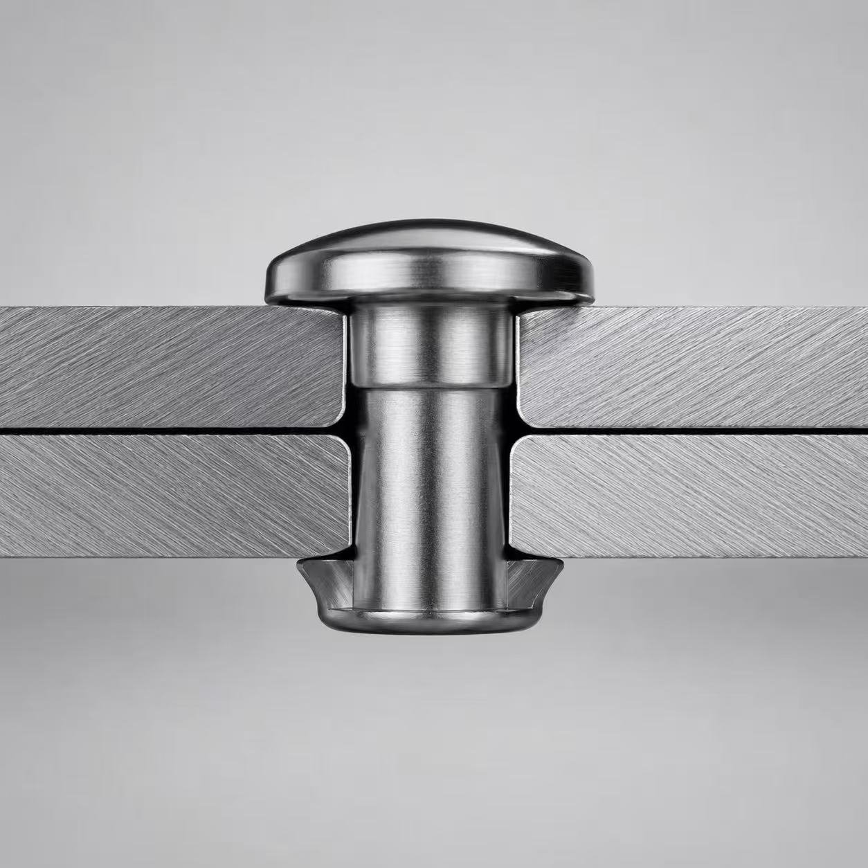
Orbital forming delivers exceptional retention performance because it shapes metal without creating internal micro-fractures. Because the tool rolls the metal gradually, the grain structure of the steel curves smoothly into the new head profile. This continuous grain flow gives the formed head high structural strength.
To guarantee consistent retention on an automated line, combine an orbital riveting machine with closed-loop height and force monitoring. A digital linear transducer measures the exact position of the forming head throughout the stroke. The machine applies pressure until the tool reaches a set displacement height relative to the top plate. This control system compensates for normal manufacturing variations in total plate thickness.
The HZX-O04TP pneumatic tabletop orbital riveting machine uses fine stroke limiters to lock in head dimensions accurately. If a rivet shank is too short, the machine detects a drop in forming force and flags the defective part automatically before it leaves the cell.
Force Correlation and Acceptance Criteria
There is a direct mathematical relationship between the final forming force applied by the machine and the resulting push-out strength of the finished joint. During trial testing, build thirty sample parts at different force levels. Pull each sample apart on a tensile testing rig. Record the maximum push-out force for every sample.
Use this testing data to establish upper and lower force limits on your production machine. Set these limits as automated pass/fail criteria inside your quality monitoring system. Every joint formed within this validated force window will meet your engineering strength standards.
VI. Resistance to Vibration and Shear Loads
Shear force acts parallel to the contact faces of the joined plates. It tries to slide the top plate across the bottom plate. Dynamic vibration creates cyclic stress that rattles joint components back and forth thousands of times per minute. Examples include automotive suspension brackets, pump enclosures, industrial motor housings, and agricultural equipment.
The Critical Requirement: Complete Hole Fill
To resist shear loads and cyclic vibration, a joint must achieve complete hole fill. If any air gap exists between the rivet shank and the internal hole wall, the joined plates will shift slightly under load. This microscopic sliding movement creates several problems over time:
- The sharp metal edges of the plate cut into the side of the rivet shank, leading to shear fatigue failure.
- The rivet head loosens as the shifting plates wear away surface coatings.
- Vibration rattles the joint loose, causing structural failure or loud operating noise.
When you fill the hole completely, the rivet shank absorbs shear forces across its full cross-sectional area. The joint acts like a single solid block of metal.
Ranking Forming Processes by Hole-Fill Capability
Different cold forming processes expand the rivet shank to varying degrees during operation.
- Press Forming (Highest Cold Fill): A heavy hydraulic or pneumatic press pushes straight down along the rivet centerline. The extreme vertical pressure squeezes the shank sideways, expanding the metal to fill every micron of internal hole space. Press forming creates the highest shear resistance in heavy assemblies.
- Hot-Upset Forming: An electrical current heats the rivet shank right before the machine applies pressure. The hot metal flows easily into the hole, achieving dense hole fill with lower mechanical press tonnage. This process is common for thick steel pins in heavy transport equipment.
- Impact Riveting (High Fill with Solid Rivets): An impact machine drives a sharp punch into the rivet end. The fast impact generates high internal pressure that expands solid steel rivet shanks effectively. High-tonnage units like the HZX-R250SA heavy-duty automatic twin riveting machine and the HZX-DR5TDA 5-ton heavy-duty automatic double head riveting machine deliver uniform impact force across twin rivet locations. This setup ensures equal hole fill in structural brackets.
- Orbital and Radial Forming (Lower Shank Expansion): Because orbital tools form metal only at the top tip of the shank, they do not expand the lower shank inside the hole as much as a direct press. If you use orbital forming for a high-shear joint, you must specify tight hole tolerances or use an oversized rivet pin.
| Forming Method | Shank Expansion Level | Shear Load Capacity | Vibration Resistance | Recommended Rivet Type |
|---|---|---|---|---|
| Direct Pressing | Maximum (Full length expansion) | Exceptional | Excellent | Solid Steel Pin |
| Hot-Upset Forming | Maximum (Thermal softening flow) | Extreme | Exceptional | High-Carbon Steel Bolt/Rivet |
| Impact Riveting | High (Concentrated near head end) | Very Good | Good | Solid or Heavy Semi-Tubular |
| Orbital Forming | Low to Moderate | Moderate (Needs tight hole) | Fair to Good | Semi-Tubular or Shoulder Rivet |
VII. Finished-Form Clearance and Height Control within Assembly Stack-Up
Modern product designs leave very little extra room inside mechanical enclosures. Fastener heads must fit within tight space limits to clear nearby moving parts, circuit boards, or decorative outer covers. Medical equipment, consumer electronics, power tools, and automotive modules require tight vertical stack-up management.
Process Techniques for Precise Height Control
Achieving a repeatable finished joint height is challenging because sheet metal thickness varies slightly from batch to batch. If your plates are slightly thick, a rigid fixed-stroke press will over-compress the joint, distorting the assembly. If your plates are thin, the same press will leave the rivet head under-formed and loose.
You can use these machine controls to maintain accurate formed height limits:
- Distance-Proportional Orbital Forming: The machine measures down from the top face of the component rather than from an arbitrary machine base point. The tool forms the head until it reaches an exact position relative to the workpiece surface.
- Positive Mechanical Stop Collars: Heavy steel stop collars mounted around the forming spindle physically prevent the tool from traveling past a preset depth limit. This hardware setup provides bulletproof height control on fast production lines.
- Controlled Eyelet Punching: Small, low-profile fasteners like eyelets and hollow tubular rivets require controlled setting tools. Specialized equipment like the HZX-E150TA automatic tabletop eyelet punching machine and the HZX-E135TA automatic tabletop eyelet grommet machine flare small metal eyelets flat against sheet metal or fabric without distorting the surrounding surface.
- Specialized Consumer Assembly Tools: Sporting goods and wearable items need smooth, low-profile rivet heads. The HZX-R5400SP automatic roller skate base and sole riveting machine flattens rivet heads inside shoe soles to ensure user comfort and maintain clear wheel bracket spacing.
Using Force-Plus-Distance Process Intelligence
Advanced riveting machines combine force sensors and displacement encoders into a single control loop. The machine tracks both vertical position and applied pressure in real time during the forming stroke. The controller checks two critical conditions before completing the cycle:
- Did the forming tool reach the target height limit?
- Was the applied force inside the expected envelope when the tool reached that target height?
If the answer to either question is no, the machine rejects the component. This process intelligence guarantees that every joint leaving the workstation meets your exact dimensional tolerances.
VIII. The Critical Role of Part Design
Even the most advanced, high-tech riveting machine cannot save a joint if the basic part geometry fights the laws of metal forming physics. Manufacturing engineering works best when you refine part design features early in the development cycle.
Design Checklist for Production-Ready Riveted Joints
Review these critical design parameters with your engineering team before ordering tooling:
- Pre-form Stick-out Length: Set the stick-out length so the metal volume matches your desired formed head size. Keep the length tolerance tight (typically within +/- 0.1mm). Too much stick-out causes metal to fold over or form flash. Too little stick-out creates a thin, weak head.
- Hole Diameter and Entry Chamfer: Specify hole sizes that match standard drill and punch sizes. Add a small 45-degree chamfer on the entry side of the hole. This chamfer relieves stress concentrations under the rivet head and accommodates the small radius under the rivet neck.
- Material Grade and Hardness Matching: Select rivet materials that are softer than the parts being joined. A soft rivet deforms smoothly without damaging hard base plates. If you must use a hard structural rivet, anneal the rivet tail to lower the required forming force.
- Plating and Surface Coatings: Thick, brittle surface plating can crack and flake off during cold forming. Flaking plating clogs forming tools and exposes bare metal to rust. Choose ductile plating materials like zinc-nickel or apply protective coatings after the forming step.
- Stack-up Tolerance Calculations: Calculate the total tolerance stack-up by adding the maximum material thickness tolerances of all joined plates. Design your forming process to handle both the minimum and maximum stack-up condition gracefully.
You should collaborate with an experienced rivet machine supplier during your initial design phase. Companies like Hengzanxin (HZX) in Dongguan, China, bring over twenty years of hands-on factory experience to the table. Their engineering team can review your 2D drawings and 3D CAD models, point out potential forming bottlenecks, and recommend design tweaks before you finalize production tooling.
IX. From Sample Validation to Stable Production
Moving a riveted joint from an initial engineering concept to a stable, high-volume manufacturing line requires a disciplined, step-by-step workflow. Skipping validation steps leads to costly delays during factory startup.
Follow this proven six-step roadmap to bring your assembly to market safely:
- Define Functional Requirements: Document your exact performance targets. Specify required torque limits, shear strength, push-out force, and maximum head clearance dimensions on the engineering drawing.
- Select Candidate Forming Processes: Match your joint requirements to the right machinery category using the comparison tables in this guide. Decide between orbital riveting, radial forming, direct pressing, or impact methods.
- Build and Test Physical Sample Joints: Machine early prototype rivets and base plates. Send these raw workpieces to your equipment supplier for trial testing. Do not rely only on computer simulations.
- Establish the Process Window: Run trial samples across a range of machine parameters. Vary the forming pressure, stroke speed, and cycle time. Find the upper and lower operating limits where all functional requirements are met.
- Lock Machine Parameters and Add Monitoring: Save the proven operating parameters inside the machine memory controller. Turn on electronic force and displacement sensors to monitor every cycle automatically.
- Scale to Full Production Equipment: Install your validated machine setup on the production floor. Integrate automated bowl feeders, safety light curtains, and custom holding fixtures.
Working with a supplier who maintains a dedicated testing lab saves weeks of setup time. Operating from a 3,000-square-meter manufacturing facility in Dongguan, Hengzanxin provides plug-and-play assembly solutions tailored to customer workpieces. Their team builds custom feeding molds, runs pre-production trials on your actual materials, and optimizes machine settings before shipping equipment to your factory floor.
X. Conclusion and Next Steps
Achieving reliable, production-ready joints requires deliberate alignment between functional engineering goals, part geometry, and cold forming processes. No single forming method works for every industrial application. An orbital riveting machine excels at delicate articulating hinges and high-retention head forming. A heavy press machine provides the raw tonnage needed for complete hole fill and maximum shear resistance. An impact machine delivers high cycle speed for structural hardware and semi-tubular fasteners.
When you match your joint design to the physical behavior of your chosen machine, you eliminate common production headaches. You stop field failures, cut scrap rates, and maintain consistent quality across thousands of assembly cycles. Early planning and practical trial testing turn complex joint designs into simple, stable manufacturing processes.
If you are developing a new joint assembly or troubleshooting an existing line failure, reach out to an experienced partner. Contact the engineering team at Hengzanxin (HZX) today. Send your part drawings and sample workpieces to their Dongguan application lab. Their engineers will evaluate your assembly, run forming trials on real machines, and deliver a detailed technical process recommendation along with a competitive quote within 12 to 24 hours.